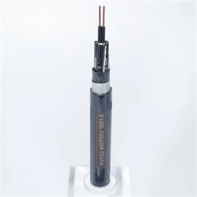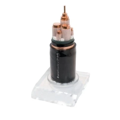

BPYJVTP2 Variable Frequency Drive Cable is designed for power transmission between variable frequency drives (VFDs) and AC motors. Its XLPE insulation, flexible copper conductor, and dual shielding system-copper wire winding plus copper tape wrapping-help control electromagnetic interference, high-frequency noise, and pulse-related disturbances generated by inverter-driven systems.
Dual-Shielding Architecture
The BPYJVTP2 designation reflects the cable's key construction:
•BP → Variable Frequency Drive Cable
•YJ → XLPE Insulation
•V → PVC Sheath
•T → Copper Wire Winding Shield
•P2 → Copper Tape Shield
The shielding system is arranged as:
Flexible Copper Conductor
↓
XLPE Insulation
↓
Non-Hygroscopic Filler
↓
Copper Wire Winding Shield
↓
Copper Tape Shield
↓
PVC Outer Sheath
The combination of copper wire winding and copper tape provides broader electromagnetic protection than a single shielding layer.
Technical Data
|
Item |
Specification |
|
Cable Type |
Variable Frequency Drive Cable |
|
Rated Voltage |
0.6/1 kV |
|
Conductor |
Flexible Copper, Class 5 |
|
Insulation |
XLPE |
|
Shielding |
Copper Wire Winding + Copper Tape |
|
Outer Sheath |
PVC |
|
Maximum Operating Temperature |
90°C |
|
Short-Circuit Temperature |
250°C, max. 5 seconds |
|
Installation Temperature |
≥0°C |
|
Minimum Ambient Temperature |
-10°C |
|
Minimum Bending Radius |
≥15 × Cable Diameter |
Standard Configurations
Available Standard Sizes: 3 × 1.5, 2.5, 4, 6, 10, 16, 25, 35, 50, 70, 95, 120, 150, 185, 240 mm².
Customized conductor sizes and cable constructions are available for different VFD and motor ratings.
|
Configuration |
Available Cross-Sectional Area |
|
3 Core |
1.5–10 mm² |
|
3 Core |
16–50 mm² |
|
3 Core |
70–240 mm² |
Electrical Performance
EMC Protection
The dual copper shielding helps suppress electromagnetic and radio-frequency interference generated by variable frequency drive outputs.
Pulse Voltage Resistance
XLPE insulation is designed to withstand the repetitive high-frequency voltage pulses associated with modern inverter systems.
Low Transfer Impedance
The copper shielding structure provides a low-impedance path for high-frequency interference, helping limit electromagnetic radiation.
Controlled Capacitance
The cable construction is designed to maintain suitable electrical characteristics for efficient transmission between the drive and motor.
Thermal Stability
XLPE insulation supports continuous operation at conductor temperatures up to 90°C and short-circuit temperatures up to 250°C for a maximum of 5 seconds.
Selection Considerations
Choosing a VFD cable should go beyond conductor size. The drive output, motor power, installation distance, EMC environment, and grounding arrangement should all be considered.
Motor Power
Select the conductor cross-sectional area according to motor current, installation conditions, and applicable electrical requirements.
Cable Length
Long VFD cable runs can increase reflected-wave and voltage-stress effects. Cable selection should therefore be coordinated with the VFD manufacturer's installation recommendations.
EMC Requirements
For installations close to PLCs, communication lines, sensors, or other sensitive equipment, a properly shielded VFD cable is preferred.
Installation Environment
Consider ambient temperature, mechanical protection, bending conditions, moisture, and routing when selecting the cable construction.
Grounding & Shield Termination
Shield effectiveness depends not only on the cable but also on proper grounding and termination. The shielding system should be installed according to the VFD and motor manufacturer's EMC requirements.
Custom Cable Engineering
BPYJVTP2 can be adapted to project-specific electrical and installation requirements.
Customized conductor cross-section
Customized core configuration
Class 5 flexible copper conductor
Copper wire and tape shielding configuration
Customized cable length
Sheath color and cable marking
OEM identification
Customized drum and export packaging
Manufacturing & Electrical Testing
Conductor Inspection
Copper conductors are checked for material consistency, diameter, stranding, and electrical resistance.
XLPE Insulation Control
Insulation thickness, concentricity, and extrusion quality are monitored during production.
Shielding Inspection
Copper wire winding and copper tape wrapping are checked for coverage, continuity, and structural consistency.
Finished Cable Testing
Finished cables undergo conductor resistance, insulation resistance, high-voltage withstand, dimensional, appearance, and other applicable electrical inspections.
Traceability
Production batches are assigned identification records, with test reports and inspection documentation available according to project requirements.
Standards & Project Compliance
BPYJVTP2 is manufactured in accordance with:
IEC 60502 - Power cables with extruded insulation
IEC 60228 - Conductors of insulated cables
IEC 60332-1 - Flame propagation testing
GB/T 12706 - Power cables with extruded insulation
Other international or project-specific standards can be considered according to customer requirements. RoHS & REACH compliant material options are also available for applicable export projects.
Delivery & Project Support
Export packaging protects the cable against moisture and mechanical damage.
Production lead time is typically 15–30 days, depending on specification and order quantity.
Technical support is available for cable selection, shielding configuration, and project documentation.
FAQ
Hot Tags: bpyjvtp2 variable frequency drive (vfd) cable, China bpyjvtp2 variable frequency drive (vfd) cable manufacturers, suppliers, factory, Armored VFD Cable, BPYJVTP2 Variable Frequency Drive VFD Cable, vfd cable, VFD Shielded Motor Cable